Arduino Uno Pinout I2C - In Depth Interfacing An I2c Lcd With Arduino / I see on arduino uno there is twice sda and sdl:
Get link
Facebook
X
Pinterest
Email
Other Apps
Arduino Uno Pinout I2C - In Depth Interfacing An I2c Lcd With Arduino / I see on arduino uno there is twice sda and sdl:. Through the i2c protocol, the data will be communicated from the 1na219 to the arduino and then the information will be displayed on the oled screen with the assistance of the same protocol. On the arduino boards with the r3 layout (1.0 pinout), the sda (data line) and scl (clock line) are on the pin headers close to the aref pin. Im looking at the pinout of the atmega328p and it uses a5 and a4 for sda and scl. Oled i2c display interfacing with arduino When using an arduino for any project, one of the main areas of concern is the limited inputs and outputs (i/o).
This oled display works on i2c communication, so it has only four pins. In r3 of original arduino uno, there are two more pins near digital io pin 13 (near the usb socket), dedicated to sda and scl. Secondary pins are mostly communications pins such as i2c and spi. The code segment below is a complete sketch ready for downloading to your arduino. The a4 pin acts as sda while the a5 pin acts as scl.
In Depth Interface Oled Graphic Display Module With Arduino from lastminuteengineers.com Secondary pins are mostly communications pins such as i2c and spi. Pin connections are as follows for wiring the oled display to an arduino uno. I've been working on building the pieces that i need to make myself a cnc pcb mill for a little while now and the next part of the puzzle is trying to get the arduino to control 3 step motors simultaneously. It's usually used to communicate between components on motherboards in cameras and in any embedded electronic system. To make it simple, in this scenario the raspberry pi will impose 3.3v, which is not a problem for the arduino pins. The versatility of the pinout provides many different options such as driving motors, leds, reading sensors and more. The 2 first pins side to usb connector are sda/scl according to documentation. That takes up a lot of pins, so i'm going to use an i2c enabled lcd because it only needs 4 wires to connect to the arduino.
So i am converting my project to run off a standalone atmega328p but i am a little confused about the i2c bus.
On the arduino uno r3, there are dedicated sda and scl pins, which i am using for my i2c devices. Gnd goes to ground pin; Sda(serial data) carries the data. On the arduino boards with the r3 layout (1.0 pinout), the sda (data line) and scl (clock line) are on the pin headers close to the aref pin. Raspberry pi pinout guide | arduino uno pinout guide. Oled 128x32 i2c display pinout. So solder it with the help of the image given below The code segment below is a complete sketch ready for downloading to your arduino. The arduino uno pinout consists of 14 digital pins, 6 analog inputs, a power jack, usb connection and icsp header. I am trying to create an i2c communication bus with an arduino uno. To use an i2c enabled lcd on the arduino, you'll need to install the liquidcrystal i2c library by marco schwartz. So i am converting my project to run off a standalone atmega328p but i am a little confused about the i2c bus. The a4 pin acts as sda while the a5 pin acts as scl.
If you're using another arduino, google the pinout and look for sda and scl pins. Arduino uno is a microcontroller board based on the atmega328p.it has 14 digital input/output pins (of which 6 can be used as pwm outputs), 6 analog inputs, a 16 mhz ceramic resonator, a usb connection, a power jack, an icsp header and a reset button. I see on arduino uno there is twice sda and sdl: It's usually used to communicate between components on motherboards in cameras and in any embedded electronic system. The module uses spi, i2c and uart protocol.
I2c Liquid Crystal Displays Arduino Project Hub from hacksterio.s3.amazonaws.com In r3 of original arduino uno, there are two more pins near digital io pin 13 (near the usb socket), dedicated to sda and scl. When using an arduino for any project, one of the main areas of concern is the limited inputs and outputs (i/o). Secondary pins are mostly communications pins such as i2c and spi. The arduino uno board is divided into digital pins, analog pins and power pins. It is used to synchronize all data transfers over the i2c bus. I will discuss about the pins of arduino uno in the arduino uno pinout section. Can t get i2c to work on an arduino nano pinout diagrams big which pins should i take for i2c on arduino uno stack overflow arduino uno i2c bus You'll also find the same situation with the spi bus pins.
The image below shows how to connect the geekcreit 0.96 inch oled i2c display to arduino.
If you're using another arduino, google the pinout and look for sda and scl pins. Upload the i2c scanner code to arduino uno. On the arduino uno r3, there are dedicated sda and scl pins, which i am using for my i2c devices. (for example, google arduino mega pinout, and check the images). So i do not understand which pins i can use. Can t get i2c to work on an arduino nano pinout diagrams big which pins should i take for i2c on arduino uno stack overflow arduino uno i2c bus But if you have a 16x2 lcd and a i2c module see the step to connect this module to lcd. Im looking at the pinout of the atmega328p and it uses a5 and a4 for sda and scl. There are pins with secondary functions as listed below. The arduino micro is a miniature version of the arduino leonardo board. As arduino uno is based on atmega328p microcontroller, the technical specifications of arduino uno are mostly related to the atmega328p mcu. Maybe it's a very old shield from before the new arduino pinout was established. This library is nice because it includes most of the functions.
The arduino micro is a miniature version of the arduino leonardo board. The arduino due has two i2c / twi interfaces sda1 and scl1 are near to the aref pin and the additional one is on pins 20 and 21. Pin connections are as follows for wiring the oled display to an arduino uno. Arduino uno pinout the arduino uno has a lot of different pins and therefore we want to go over the different kinds of pins. The arduino uno board is divided into digital pins, analog pins and power pins.
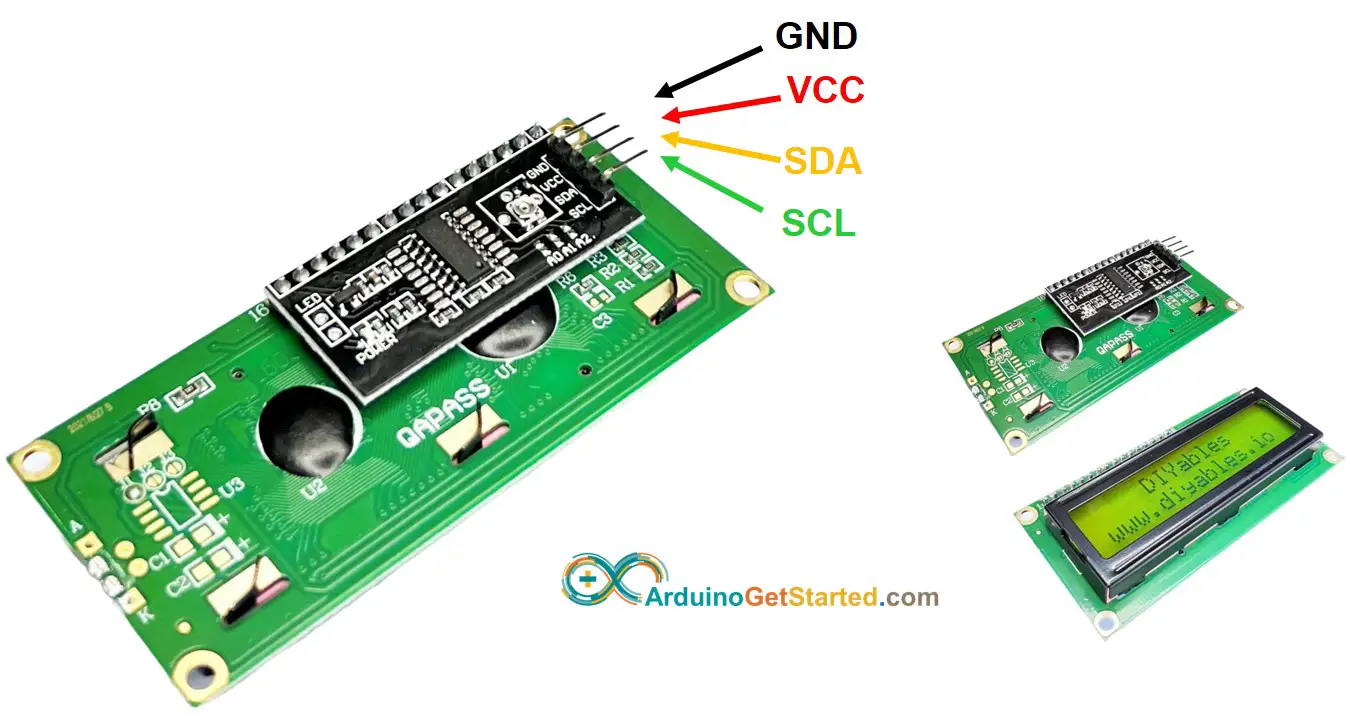
Arduino Lcd I2c Arduino Tutorial from arduinogetstarted.com First solder the i2c module. Gnd goes to ground pin; So i do not understand which pins i can use. Any well designed shield will use those pins rather than assuming i2c is on a4 and a5. When using an arduino for any project, one of the main areas of concern is the limited inputs and outputs (i/o). Geekcreit 0.96 inch oled display i2c/twi pinout. Sda(serial data) carries the data. But if you have a 16x2 lcd and a i2c module see the step to connect this module to lcd.
If you take a look at the pinout of arduino uno from the tutorial arduino uno pinout, analog input pins a4 and a5 have an alternative function of i2c.
I've been working on building the pieces that i need to make myself a cnc pcb mill for a little while now and the next part of the puzzle is trying to get the arduino to control 3 step motors simultaneously. And the documentation says a4 and a5 pins can also be sda/scl. To use an i2c enabled lcd on the arduino, you'll need to install the liquidcrystal i2c library by marco schwartz. Pin connections are as follows for wiring the oled display to an arduino uno. This oled display works on i2c communication, so it has only four pins. I see on arduino uno there is twice sda and sdl: This project will read the position of a potentiometer connected to a master arduino, send the information over i2c, and change the blink rate of the led on the slave arduino. In this post, we'll go over the capabilities of the arduino uno. In our last two posts, we focused on the software aspects of the arduino. The versatility of the pinout provides many different options such as driving motors, leds, reading sensors and more. In r3 of original arduino uno, there are two more pins near digital io pin 13 (near the usb socket), dedicated to sda and scl. Gnd goes to ground pin; Im looking at the pinout of the atmega328p and it uses a5 and a4 for sda and scl.
On the arduino boards with the r3 layout (10 pinout), the sda (data line) and scl (clock line) are on the pin headers close to the aref pin arduino uno pinout. Secondary pins are mostly communications pins such as i2c and spi.


Comments
Post a Comment