Arduino Uno Pinout Pwm - Buy Arduino Pro Micro Clone 5V 16 Mhz with cheap price - In arduino, the pwm enabled pins produce a constant frequency of ~ 500hz, while the duty cycle changes according to the parameters set by the user.
Get link
Facebook
X
Pinterest
Email
Other Apps
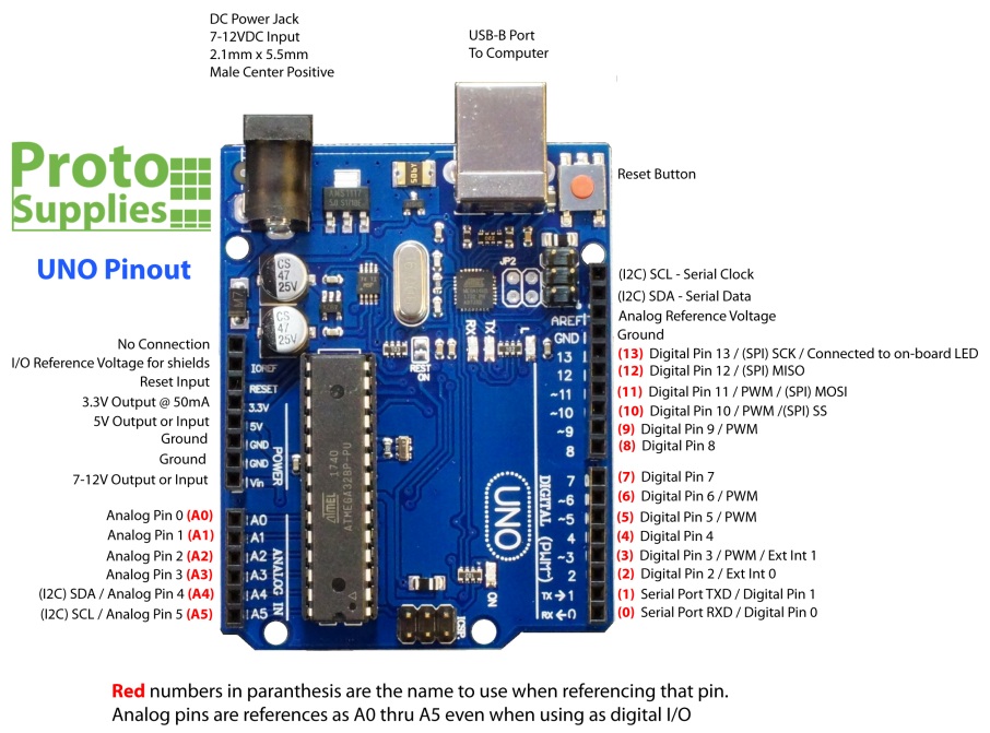
Arduino Uno Pinout Pwm - Buy Arduino Pro Micro Clone 5V 16 Mhz with cheap price - In arduino, the pwm enabled pins produce a constant frequency of ~ 500hz, while the duty cycle changes according to the parameters set by the user.. Six of the 14 digital i/o pins are able to produce a pwm signal. Arduino uno pinout and board description arduino uno is an electronic experimental board. But we can use only one function of each pin at a time. :) so, design a simulation in proteus as shown in the below figure: Secondary pins are mostly communications pins such as i2c and spi.
Pin number, 5, 6, 9, 10, and 11 provide pwm output. In arduino, the pwm enabled pins produce a constant frequency of ~ 500hz, while the duty cycle changes according to the parameters set by the user. Six of the 14 digital i/o pins are able to produce a pwm signal. As you can see in the above figure that i have used ldr sensor with arduino uno and i have plotted the pwm output coming from arduino uno. A pwm (pulse width modulation) is basically a way to get a specific voltage (ex:
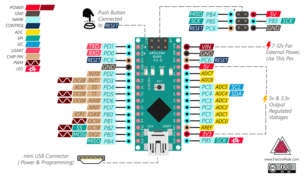
Uno R3 with ATmega16U2 USB - ProtoSupplies from protosupplies.com Arduino micro has 20 digital i / o pins (7 of which can be used as pwm output, 12 of which can be used as analog signal. Then, a duty cycle parameter will tell what percentage of each pulse is in the high. In arduino, the pwm enabled pins produce a constant frequency of ~ 500hz, while the duty cycle changes according to the parameters set by the user. There can be many arduino except arduino's official products. Using these pwm pins, you can create the pwm pulse which we are gonna do rite now. Six of the 14 digital i/o pins are able to produce a pwm signal. Pwm stands for pulse width modulation and it is a technique used in controlling the brightness of led, speed control of dc motor, controlling a the arduino digital pins either gives us 5v (when turned high) or 0v (when turned low) and the output is a square wave signal. :) so, design a simulation in proteus as shown in the below figure:
Secondary pins are mostly communications pins such as i2c and spi.
Development board has 14 gpio pin. Arduino uno pinout and board description arduino uno is an electronic experimental board. Suppose you want a dc motor to run at a certain analog voltage between 0 and 5 v. The detailed description of each feature is out of the scope of this post but will be discussed in detail later in the next post. Then, a duty cycle parameter will tell what percentage of each pulse is in the high. Six of the 14 digital i/o pins are able to produce a pwm signal. Pwm stands for pulse width modulation. This is not possible because. So if we want to dim. Pin configuration description and their use. Arduino is an open source project. Arduino uno power supply pinout: Arduino uno pinout diagram pinout diagram shows that each pin has multiple functions such as pwm interrupts general purpose input output and.
But, only six of them have a pulse width modulation feature. We can use these pins, as analog out/we can control the motor at different speeds. The discussion about the pwm phenomenon and the application of. Pin number, 5, 6, 9, 10, and 11 provide pwm output. Arduino is an open source project.
راهنمای خرید آردوینو 2020: چگونه بهترین برد را برای پروژه ... from thecaferobot.com Using these pwm pins, you can create the pwm pulse which we are gonna do rite now. Arduino uno power supply pinout: Arduino is an open source project. Pin number, 5, 6, 9, 10, and 11 provide pwm output. Then, a duty cycle parameter will tell what percentage of each pulse is in the high. 4.1v) with only high/low (5v/0v) states. There can be many arduino except arduino's official products. If you want to communicate between multiple devices you need communication pins which are also provided by the arduino.
We can use these pins, as analog out/we can control the motor at different speeds.
A pwm (pulse width modulation) is basically a way to get a specific voltage (ex: Using these pwm pins, you can create the pwm pulse which we are gonna do rite now. But, only six of them have a pulse width modulation feature. Arduino uno power supply pinout: But we can use only one function of each pin at a time. Find arduino uno pin diagram, pin configuration, technical specifications and features arduino uno has 14 digital input/output pins (out of which 6 can be used as pwm outputs), 6 analog input pins, a arduino ide (integrated development environment) is required to program the arduino uno board. Pwm stands for pulse width modulation and it is a technique used in controlling the brightness of led, speed control of dc motor, controlling a the arduino digital pins either gives us 5v (when turned high) or 0v (when turned low) and the output is a square wave signal. We can use these pins, as analog out/we can control the motor at different speeds. This symbol denotes that these pins are the pwm (pulse width modulation pins). The discussion about the pwm phenomenon and the application of. The arduino uno has a lot of different pins and therefore we want to go over the different kinds of pins. This is not possible because. Arduino uno pinout and board description arduino uno is an electronic experimental board.
We use digital out as high or low even with pwm outputs function. 4.1v) with only high/low (5v/0v) states. If you want to communicate between multiple devices you need communication pins which are also provided by the arduino. But, only six of them have a pulse width modulation feature. Arduino micro has 20 digital i / o pins (7 of which can be used as pwm output, 12 of which can be used as analog signal.
Arduino Uno Pinout from www.electroschematics.com There can be many arduino except arduino's official products. It means, that an analog value is being modulated on a digital signal. We use digital out as high or low even with pwm outputs function. But we can use only one function of each pin at a time. This is not possible because. This symbol denotes that these pins are the pwm (pulse width modulation pins). If you want to communicate between multiple devices you need communication pins which are also provided by the arduino. Arduino micro is using atmega32u4 processor.
Pin number, 5, 6, 9, 10, and 11 provide pwm output.
We use digital out as high or low even with pwm outputs function. This symbol denotes that these pins are the pwm (pulse width modulation pins). Using these pwm pins, you can create the pwm pulse which we are gonna do rite now. Development board has 14 gpio pin. There can be many arduino except arduino's official products. Pwm stands for pulse width modulation. Pwm stands for pulse width modulation and it is a technique used in controlling the brightness of led, speed control of dc motor, controlling a the arduino digital pins either gives us 5v (when turned high) or 0v (when turned low) and the output is a square wave signal. Barrel jack, usb port, and vin pin. Arduino micro has 20 digital i / o pins (7 of which can be used as pwm output, 12 of which can be used as analog signal. It means, that an analog value is being modulated on a digital signal. Pin configuration description and their use. Arduino uno power supply pinout: Arduino is an open source project.
Pin configuration description and their use arduino uno pinout. Six of the 14 digital i/o pins are able to produce a pwm signal.

Comments
Post a Comment